ROLLER ROCKER GENERAL FITTING INSTRUCTIONS
Download fitting Instructions PDF.
For all: Street Terra, Ultralite, Ultralite Pro, Pro Street & Platinum Roller Rockers
These Rockers are designed to fit catalogue applications, using basically standard components with minimum attention to fitment. However, as we have no control over engine assembly or the large variety of available components, caution must be exercised to ensure free operation and correct rocker geometry, for maximum benefit from these products. Failure to carry out these checks voids any implied or expressed warranty.
IMPORTANT: All Yella Terra Roller Rockers must be soaked overnight in engine oil prior to installation.
STUD MOUNT ROCKER CHECKING PROCEDURE
Clearance and geometry checks cannot be properly carried out with hydraulic lifters fitted. If hydraulic lifters are to be used then solid lifters of the same height will be required to perform the following checks.
Check for minimum .060” (1.5mm) clearance between larger than standard valve springs/retainers and rocker armpit. Note: Grinding or machining this area can weaken the arm and will void warranty.
It is desirable to have the least possible amount of roller movement across the valve tip as possible. This will provide maximum valve lift and minimum wear and side loading of the valves and guides.
To determine the roller movement across the valve tip, known as the “rocker strike” or “contact patch”, apply a thin smear of bearing blue (prussian blue) to the valve tip, fit the rocker arm and set lash clearance. For engines fitted with hydraulic lifter cams, set the clearance to zero.
Rotate the engine by hand at least one full turn watching the roller movement across the valve, the roller should move forward across the tip until half lift then back to its starting position at full lift.
The “rocker strike” or “contact patch” should be central on the valve unless non standard length valves are fitted due to the intersecting angles of the stud and valve centrelines.
Geometry can be changed by fitting different length pushrods or valve lash caps, shorter pushrods or lash caps will bring the starting point further back from the centre of the valve, longer pushrods will have the opposite effect.
Ideal geometry will have a strike area of approximately .060” (1.5mm) wide, central on the valve and have the major amount of the roller movement at low lift where the spring pressure is least.
Before running the engine it is vital to ensure free operation and at least .060” (1.5mm) of clearance between arm and valve spring, retainer, base of rocker stud and back of posilock nut. Clearance should be checked at both closed and fully open valve positions.
SPECIAL NOTE FOR STUD GIRDLE APPLICATIONS
Posilocks must not exceed .560” (14.2mm) diameter at base or damage to inner bearing cages will result.
“EASY FIT” ROCKERS (EF)
These rockers are designed to be fitted as a replacement of the original arms using the OEM sized mounting hardware. Due to variances in engine combinations, we cannot guarantee that the standard pushrod length will be correct. It is imperative that you check your pushrod length during installation.
- Place engine on top dead centre number one cylinder (both valves closed).
- Remove old rockers, pivots and bolts. Discard steel aligning channels fitted to some Ford Windsor and GM engines.
- Fit new rockers and tighten capscrews evenly until all freeplay is taken up and you cannot easily turn the pushrods with your fingers. This is the “Zero Free Play” point.
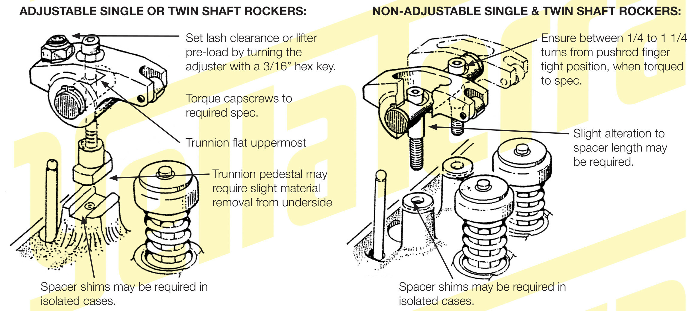
- Taking note of the zero free play starting point, evenly tighten the screws to 25ft lb, ideally this should be between 1/2 and 3/4 of a turn. More than 1 1/2 will require the installation of shims supplied in kit to reduce the lifter pre-load. In unusual circumstances, less than 1/4 turn will require shortening of the pedestals or shims to increase lifter pre-load.
- Repeat with remaining cylinders at top dead centre (both valves closed) in firing order. Liberally oil rollers, bearings and pushrod adjusters. Allow time for the lifters to bleed down on last cylinder before cranking engine.
SPECIAL NOTE FOR ADJUSTABLE KITS
Back off adjusting screws fully and install rockers as described in step 3, however now clearance should exist. Manufacturers lash can be set for solid lifter camshafts or normal hydraulic lifter pre-load of 1/2 - 3/4 turn of adjuster can be set.
Tighten lock nuts to maximum 20ft lb. Do not over tighten.

NOTES: Engines with non-standard components, particularly reground camshafts or non standard valve lengths may require modification to support the pedestal height, either by machining or grinding to shorten or by adding shims to lengthen. Shaft Mount rockers don’t require pushrod guideplates.
Taller aftermarket rocker covers, or modified standard rocker covers may be required to allow clearance for the adjusting screw and nut at full lift. In some cases, clearance can be achieved by using two gaskets glued together with a contact adhesive and longer bolts, when taller covers are not available or desired.
PLATINUM SINGLE & TWIN SHAFT ROCKERS

Unlike stud mount rockers, the shaft rocker geometry cannot be adjusted by changing pushrod length. Changes can only be made, by altering the shaft height relative to the valve tip. This is done by fitting taller pedestals, shims, or plates to raise the shaft height. Fitting shorter pedestals or machining supplied pedestals will lower shaft height.
To determine required shaft height, we recommend using the “rocker strike” or “contact patch” method. The easiest method is to not have the heads fitted to the engine, but by bench checking, which can easly be carried out with valves and light checking springs fitted.
For unique single shaft system rockers, refer to Platinum brochure or website for fitting procedure.
Bolt at least one of each inlet and exhaust rocker to head for single shaft or one pair for twin shaft.
Pedestals supplied are to suit standard length valves, as catalogued, extra length valves require longer pedestals. [see 3 below]
Do not fit pushrods guide plates with any single or twin shaft rocker system.
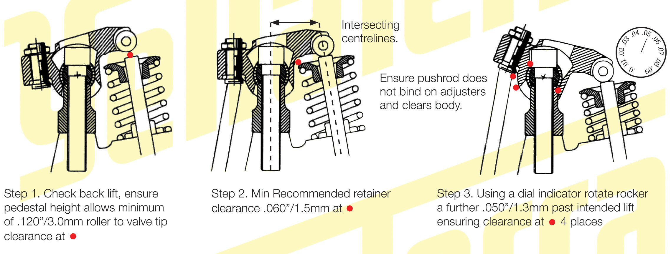
- Check that shaft bolt hole spacing matches cylinder heads and that rockers can rotate freely to allow valve to close leaving enough clearance to set lash. Minimum recommended .120” (3.0mm).
- Check for sufficient clearance between larger than standard valve springs and retainers and front of rocker arm. NB Grinding or machining in this area can weaken arm and will void warranty.
-
Lightly smear bearing blue (Prussian blue) on valve tip; gently tap rocker arm onto valve tip to leave a line with the blue. This line should be slightly toward the pushrod side of the valve centre when shaft height is correct.
Extra length valves will alter the position of the contact patch across the valve due to the intersecting angles of the centrelines of the stud bolt hole and valve guide (see 2 above) - taller pedestals, spacers or shims will be required to achieve a narrow contact patch. This may cause the roller tip to not be exactly central on the valve, this will be functionally acceptable.
- Rotate rocker by hand until valve opens to intended lift, watching roller movement on valve tip. When shaft height is ideal roller will move forward, past the centre of the valve tip and back towards its starting position as the valve reaches full lift.
-
Remove rockers and measure the width of the contact patch. .060” (1.5mm) or less is the goal in most cases but the higher the valve lift the greater the width will be. In many instances .080” (2.0mm) or .090” (2.2mm) is quite acceptable.
The movement of the roller across the valve should be gradual and as even as possible. A wide patch and excessive lateral movement at the start of the valve opening indicates shaft position is too low, and a wide patch with excessive lateral movement toward full lift indicates shaft position is too high.
- Once shaft height has been determined carefully check again for free operation and specified clearance in both, valve open and valve closed positions, paying special attention to the head of the mounting bolt and the internal machining of the rocker arms, as noted in drawings.
- When checking for pushrod length and certainly in operation, it is most desirable to have adjusting screws no more than one and a half turns out from the fully backed off position.
NOTE: On single shaft applications, the shaft heights are usually set in groups of inlet and exhaust. Twin shafts must be set in pairs, as shaft must remain parallel to head for correct operation.
FURTHER TECHNICAL TIPS
All rocker arms have a limit to their rotation, at some point the arm will hit on the stud, posilock, pedestal or head of the retaining bolt. It is vital to ensure the operating range of the rockers on each engine configuration is within these limits to avoid severe damage.
Poor quality aftermarket pushrods can burn up adjusters and pushrod ends, therefore it is advisable to ensure they have the correct shape and size ends. Bearing blue can be used to check that pushrod end matches rocker adjuster or cup. Swaged end one piece pushrods should be checked for binding in cup or adjuster at full lift, as they do not allow as much rotation as ball end pushrods.
On increased ratio rockers, the pushrod cup or adjuster is moved closer to the centre of the arm. This may require additional clearance in cylinder head pushrod holes and guideplates where fitted.
TORQUE SETTINGS
| 5/16” CAPSCREW | 20-25ft lb | M8 CAPSCREW | 20-25ft lb |
| 3/8” CAPSCREW | 35-40ft lb | M10 CAPSCREW | 35-40ft lb |
| 7/16” CAPSCREW | 50-55ft lb | ||
ALL WITH UNDERSIDE OF CAPSCREW HEAD OILED
| 3/8” ADJ LOCKNUTS | 20 ft lb |
| 3/8” & 7/16” POSILOCKS | Set lash at .002” larger than required. Tighten grub screw to 15ft lb. Tighten grub screw and posilock nut together to required lash. |
